


Smart Wind Turbine
Smart Horizontal Wind Turbine:The horizontal-axisturbine typically has a three-blade vertical propeller that catches the wind face-on. To work properly, the horizontal-axis turbine needs the wind to flow at a right angle to the blades. If it blows from a different direction than the blades are facing, the turbine gets much less energy from the wind. To accommodate changes in wind direction, the turbine has a yaw drive that rotates the unit’s direction. However, the drive adapts slowly to changing directions because it must turn the entire turbine and propeller assembly. We can supply in many size starting from model AR-100W to AR-30KW
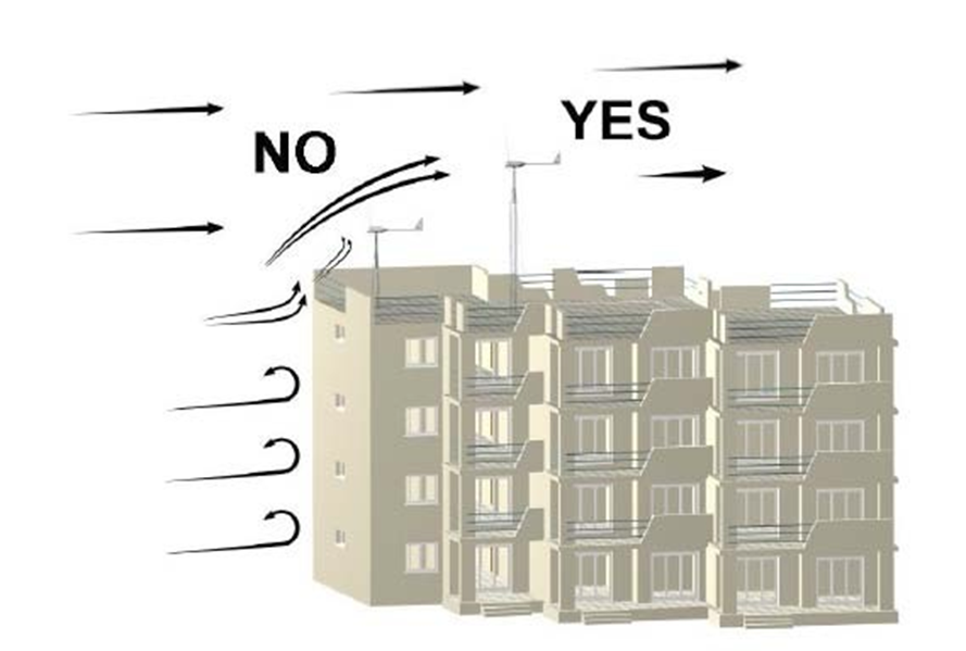
Smart Vertical Wind Turbine: The vertical turbine has a set of blades that spins around a vertical axis.Vertical turbine runs well regardless of wind direction, making it better-suited to urban areas with tall buildings where wind turbulence is a given. The vertical-axis design allows it to operate on lower wind speeds than is possible with the horizontal turbine. We can supply size only in two models at present VAR-120W and VAR-1000W.
We are providing you with the details of the turbine size, installation and maintenance manual with price list.

Technical and Performance Specification
|
200W |
500W |
1KW |
2KW |
5KW |
7.5KW |
20KW |
30KW |
|
SYSTEM |
||||||||||
|
TYPE |
Battery charger |
Battery charger |
Battery charger |
Battery Charger or Grid Tied |
Battery Charger or Grid Tied |
Battery Charger or Grid Tied |
Battery Charger or Grid Tied |
Battery Charger or Grid Tied |
||
|
PERFORMANCE PARAMETERS: |
||||||||||
|
Rated Electrical Power |
200 W @ 9.7 m/s |
500W @9.5 m/s |
1000 W @ 9.7 m/s |
2000 W @ 9.5 m/s |
5000 W @ 9.5 m/ |
7500 W @ 9.7 m/s |
20000W @ 10.5m/s |
30000W @ 10.7m/s |
||
|
Rated Wind Speed |
9.2 m/s |
9.5 m/s |
9.7 m/s |
9.5 m/s |
9.5 m/s |
9.7 m/s |
10.5 m/s |
10.5 m/s |
||
|
cut-in |
3.5 m/s |
3.0 m/s |
3.5 m/s |
3.5 m/s |
3.5 m/s |
3.5 m/s |
3.5 m/s |
3.5 m/s |
||
|
shut-down (high wind) |
23 m/s |
23 m/s |
23 m/s |
23 m/s |
23 m/s |
23 m/s |
23 m/s |
23 m/s |
||
|
Peak (survival) |
60 m/s |
60 m/s |
60 m/s |
60 m/s |
60 m/s |
60 m/s |
60 m/s |
60 m/s |
||
|
ROTOR |
||||||||||
|
Type of Hub |
Fixed Pitch |
Fixed Pitch |
Fixed Pitch |
Fixed Pitch |
Fixed Pitch |
Fixed Pitch |
Fixed Pitch |
Fixed Pitch |
||
|
Rotor Diameter |
1.5 m |
2 m |
3.2 m |
4.5 m |
6.8 m |
7.5 m |
10.5m |
13.9 m |
||
|
Swept Area |
1.766 m2 |
3.14 m2 |
8.03 m2 |
15.8 m2 |
36.3 m2 |
44.2 m2 |
86.54 m2 |
151.5 m2 |
||
|
Number of Blades |
3 |
3 |
3 |
3 |
3 |
3 |
3 |
3 |
||
|
Rotor Speed @ rated wind speed |
500 RPM |
500 RPM |
340 RPM |
250 RPM |
167 RPM |
150 RPM |
140 RPM |
88 RPM |
||
|
Location Relative to Tower |
Up Wind |
Up Wind |
Up Wind |
Up Wind |
Up Wind |
Up Wind |
Up Wind |
Down Wind |
||
|
Rotor Tip Speed |
39.25 m/s |
52.3 m/s |
56 m/s |
58 m/s |
47 m/s |
47 m/s |
47 m/s |
47 m/s |
||
|
Design Tip Speed |
5.5 |
6 |
6.5 |
7 |
7 |
7 |
7 |
7 |
||
|
Length |
0.65 m |
0.85 m |
1.5m |
2 m |
3.2 m |
3.2 m |
5 m |
6.6 m |
||
|
Material |
Glass Fiber |
Glass Fiber |
Glass Fiber |
Glass Fiber |
Glass Fiber |
Glass Fiber |
Glass Fiber |
Glass Fiber |
||
|
Airfoil (type) |
NACA23015 modified |
NACA 23015 modified |
NACA 23015 modified |
NACA 23015 modified |
NACA 23015 modified |
NACA 23015 modified |
NACA 23015 modified |
NACA 23015 modified |
||
|
Twist |
14° outer blade |
14° outer blade |
14° outer blade |
14° outer blade |
14° outer blade |
14° outer blade |
16° outer blade |
16° outer blade |
||
|
Root Chord |
55 mm |
70 mm |
80 mm |
100 mm |
130 mm |
130 mm |
150 mm |
440 mm |
||
|
Max Chord |
100 mm |
100 mm |
100 mm |
140 mm |
370 mm |
370 mm |
450 mm |
680 mm |
||
|
Tip Chord |
60 mm |
75 mm |
80 mm |
105 mm |
150 mm |
150 mm |
160mm |
250 mm |
||
|
Blade TrailingEdge |
Parabolic |
Parabolic |
Taper and straight |
Parabolic |
Parabolic |
Parabolic |
Tapered and Straight |
Tapered and Straight |
||
|
System Weight |
35 -Kg |
60 kg |
90 Kg |
170 Kg |
320 Kg |
370 Kg |
950 Kg |
1500 Kg |
||
|
Blade Weight -approx. |
1.5 kg |
2 kg |
8 kg |
15 kg |
33 kg |
33 kg |
75 Kg |
120 Kg |
||
|
GENERATOR |
|||||||||
|
Type |
PMDC |
PMDC |
PMDC |
PM Alternator |
PM Alternator |
PM Alternator |
PM Alternator |
PM Alternator |
|
|
Voltage for Grid Tied system |
415 - 3 Phase |
415 - 3 Phase |
415 - 3 Phase |
415 - 3 Phase |
415 - 3 Phase |
||||
|
Voltage for Battery Charge Sys |
12 Volt DC |
24 Volt DC |
24 / 48 – Volt DC |
48 - Volt - Single Phase |
230 - Single Phase |
230 - Single Phase |
415 - 3 Phase |
415 - 3 Phase |
|
|
RECTIFIER |
|||||||||
|
Rectifier |
Not applicable |
Not applicable |
Not applicable |
Applicable |
Applicable |
Applicable |
Applicable |
Applicable |
|
|
Output Voltage |
150 DC to 550 DC |
150 DC to 550 DC |
150 DC to 550 DC |
150 DC to 550 DC |
150 DC to 550 DC |
||||
|
Watts @ Rated Wind Speed |
200 Watts |
500 Watts |
1000 Watts |
2000 Watts |
5000 Watts |
7500 Watts |
20000 Watts |
30000 Watts |
|
|
Rated Generator RPM |
500 |
500 |
340 |
250 |
170 |
150 |
150 |
400 |
|
|
Speed RPM (nominal) |
500 |
500 |
400 |
250 |
200 |
200 |
200 |
400 |
|
|
Battery Bank (Min) |
|||||||||
|
12-V 42 AH - 1 No |
12-V 42 Ah - 2 |
12-V 70 Ah - 4 Nos |
12 - V100 Ah - 4Nos |
12 - V 100 Ah - 10 |
12 - v 100 Ah - 10 |
12-v 150 Ah - 20 |
12-v 150 Ah – 20 Nos |
||
|
Nos |
Nos |
Nos |
Nos |
||||||
|
TRANSMISSION |
|||||||||
|
Type |
Direct Drive |
Direct Drive |
Direct Drive |
Direct Drive |
Direct Drive |
Direct Drive |
Direct Drive |
Planetary Gear Box |
|
|
Ratio (rotor to gen. speed) |
1:1 |
1:1 |
1:1 |
1:1 |
1:1 |
1:1 |
1:1 |
1:4 |
|
|
Lubrication |
Grease |
Grease |
Grease |
Grease |
Grease |
Grease |
Grease |
oil |
|
|
YAW SYSTEM |
|||||||||
|
Normal |
By Tail Vane with Slip Ring |
By Tail Vane with Slip Ring |
By Tail Vane with Slip Ring |
By Tail Vane with Slip Ring |
By Tail Vane with Slip Ring |
By Tail Vane with Slip Ring |
By Tail Vane with Slip Ring |
Down Wind with Slip Ring |
|
|
Structural |
Yaw bearing mountedon tower top |
Yaw bearing mountedon tower top |
Yaw bearing mounted on tower top |
Yaw bearing mounted on tower top |
Yaw bearing mounted on tower top |
Yaw bearing mountedon tower top |
Yaw bearing mountedon tower top |
Yaw bearing mounted on tower top |
|
|
TOWER |
|||||||||
|
Type |
Gay and Wire |
Gay and Wire or Lattice |
Gay and Wire or Lattice |
Gay and Wire or Lattice |
Gay and Wire or Lattice |
Gay and Wire or Lattice |
Gay and Wire or Lattice |
Gay and Wire or Lattice |
|
|
Tower Height |
4 m |
8 m |
10m |
12m |
15m |
18m |
25m |
30m |
|
|
Options |
8m |
10 m / 12 m |
12 m / 15 m |
15 m / 18 m / 20 m / 25 m |
18 m / 20 m / 25 m |
20 m / 25 m |
30 m |
35 m |
|
|
CONTROL SYSTEM |
|||||||||
|
Type |
PWM based |
PWM based |
PWM based |
PWM based |
PWM based |
PWM based |
PWM based |
PWM based |
|
|
Over speed Device |
Mechanical Governor |
Mechanical Governor |
Mechanical Governor |
Mechanical Governor |
Mechanical Governor |
Mechanical Governor |
|||
|
Manual Brake |
Electro Magnetic Brake |
Electro Magnetic Brake |
Electro Magnetic Brake |
Electro Magnetic Brake |
Electro Magnetic Brake |
||||
|
INVERTOR |
|||||||||
|
Type |
SquireWave |
Squire Wave |
Squire Wave |
Squire Wave |
Sin Wave |
Sin Wave |
Sin Wave |
Sin Wave |
|
|
Inverter Output Voltage |
230 V AC |
230 V AC |
230 V AC |
230 V AC |
230 V AC |
230 V AC |
415 V AC |
415 V AC |
|
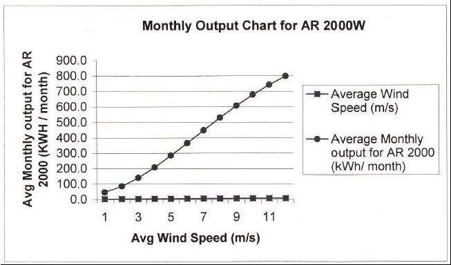
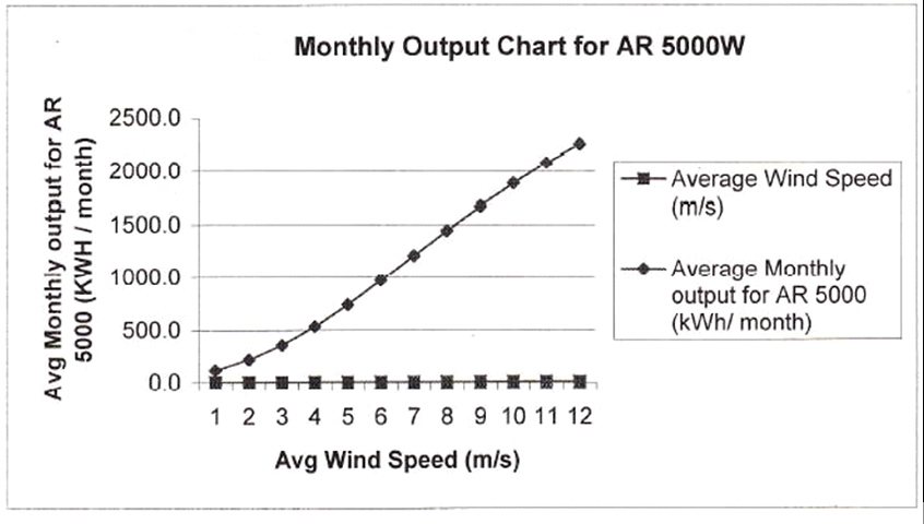
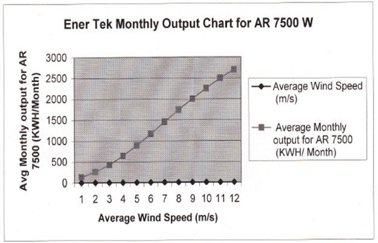
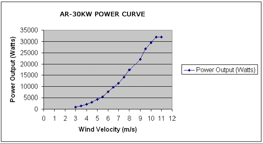
CALCULATED POWER CURVE FOR 2KW- 5KW-7.5KW – 30KW
SITE SELECTION SITE IS IMPORTANT TO EFFICIENCY AND SAFETY OF WIND TURBINE.
A good location needs 2 basic conditions
‐ High average wind speed
‐ Low turbulence
The energy we can take from the wind is proportional to the cube of its speed. This basically means that when the wind doubles its speed, the power we can produce is up to 8 times higher.
Therefore, the best site to install a windmill will be a place where it is exposed to the most constant and highest wind speed possible. The wind speed depends enormously on the landscape the air moved over. In almost all locations the wind speed increases, as you get higher off the ground, vegetation, landscape, nearby buildings etc. stop the wind and produce turbulences.
Please read Annex III – for more details about this.
Tower (Pole) installation
The anchoring of the tower will depend on the kind of tower you will be using. The foundation for the self-standing towers is very important, and for the tilt-up tower is just to avoid it sinking on the ground. For both cases, check that at all moment the tower remains totally vertical.
If your tower is not strong enough, you must reinforce it using guy ropes. If the ground is not strong, remember to use a correct size for basements. Check that, at all time your tower remains perfectly vertical.
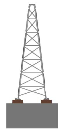
For Lattice type tower will be installed at site based on the numbering of each member. Each model foundation drawing will be very depends the soil property. It is good to have soil test report before going foundation.
Lattice Tower
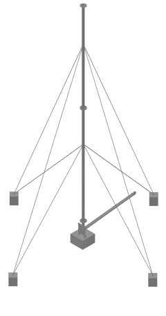
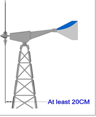
The guy ropes take all the bending moment of the tower. They therefore must be 6-10 mm diameter steel cables. Attach the guy ropes the highest on the tower but always beneath blades diameter. Grounding the tower will provide static and lightning protection for the system. This can be made driving cooper wire into the ground near the tower base and connecting it to the tower with wire. You must absolutely make sure that no object could possibly reach the blades, and that any other parts of the windmill touch any other moving part. Allow a minimum distance of 20cmbetween the blades and the tower.
|
CAUTION |
|
The windmill must be able to |
|
turn 360° freely with no |
|
Obstacles in its way. |
|
WARNING |
|
Any object touching the |
|
blades moving, will break |
|
them and will damage the |
|
system causing major |
|
Problems. |
INSTALLING THE WIND TURBINE
Installation Procedure:
To easily install the wind turbine on the tower, a bracket and pulley system should be used.
This system must securely attach to the tower, with the pulley on top. Using this method, the turbine can be hoisted up and secured while the electrical connection is completed and the turbine is fitted to the tower.
Make sure all of the other electrical connections are completed before attempting to electrically connect the turbine to the system.
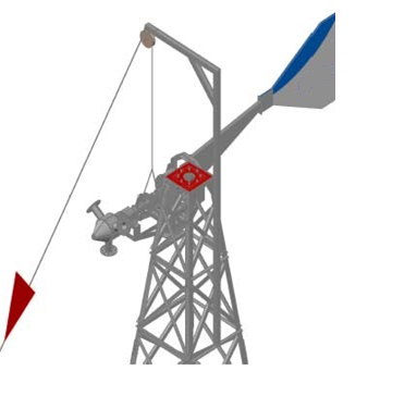
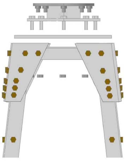
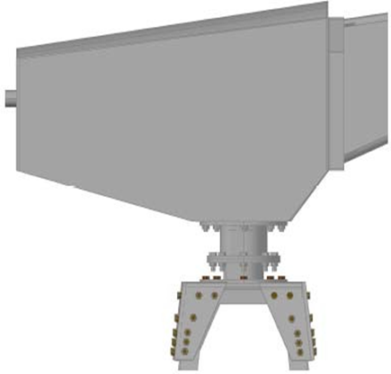
BRACKET AND PULLEY SYSTEM Yawing (Fixation) Plate
Yawing (Fixation)Plate: This plate is provided to be attached to the tower. Another one is assembled on the wind turbine base. Its function is holding the wind turbine, offering an easy way to install it and take it down from the tower at any moment.
* The bolts set and tower plate are served in an independent plastic bag, if not mailed before.
Tail
The tail is made to keep the windmill facing into the wind at any time. The tail is made of 2 different pieces:
- A fiberglass vane
- Steel Frame
*This is usually already assembled and delivered in the box
Tail vane with Alternator
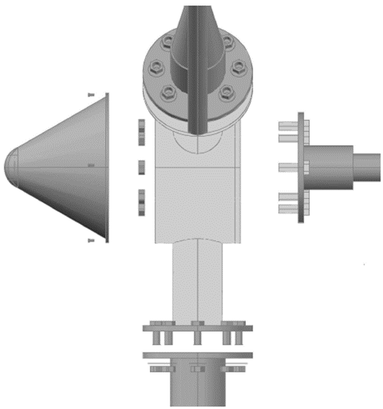
The tail is attached to the alternator Frame at this point. Before bolting the vane to the alternator, pass the body shroud through the tail vane. (Once the vane is bolted, you will not be able to install the nacelle (nose cone)).
This joint has 2 different systems to secure, one has a bolt going through the vane, and the other one is a bridle system. We first introduce the tail vane into the backside of the alternator, and make coincide the holes in both pieces.
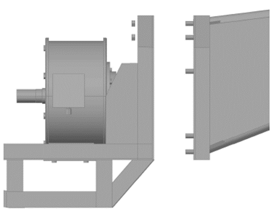
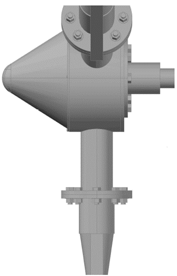
6.5 Nacelle The nacelle protects the alternator from the external climatologically agents. The nacelle is attached with various bolts, used in top, back and underneath sides.
The assemble order is:
- bolt, grower washer and wide washer the next bolt is to secure the one in the back.
Blade with Hub Unit
The blades, made out of fiberglass reinforced, are the part directly in contact with the wind. They are highly stressed. Their aerodynamics, specifically designed for USCET wind turbines, makes the alternator turn faster or slower depending on wind speed.
That assemble them to the hub according the numbering on the Blade flange, we have to place them with the set-off logo facing back, and this is facing the tail.
Charge Controller
The Charge controller is protects the batteries from high voltage. Any electric generator that can over exceed the batteries voltage requires a charge controller. The correct use of the proper charge controller is critical to good performance and long life of the battery system.
The controller continuously monitors the battery voltage and controls the current through the batteries. It allows the optimum charge to the batteries when they are low and diverts the charge to a dump load when they are fully charged. This dump load is installed within the charge controller and can be fitted with an optional water heater output.
The charge controllers USCET wind turbines use, have been specially designed to work with our machines, and solar panels in hybrid cases.
The charge controller is provided with the following connectionswitches:
- 3 phases input from the wind turbine.
- Solar panels input +/- (Optional)
- Batteries output +/-
- Water heater output (Optional)
The charge controllers are equipped with a red led. This led will be on when the batteries are fully charges and the electricity is being driver to the dump load. They are equipped, as well with a voltmeter and an amp meter to measure the electricity that is being produced at all times.
Do not connect any other electric element between the wind turbine and charge controller OR between the charge controller and the batteries, serious damage could occur.
On the left side of the charge controller, there is a break switch. This switch
short-circuits the alternator increasing the torque required to turn the rotor, thus slowing the turbine down. When this happens, the torque to make the alternator turn is much higher, this acts as a brake.
In high wind speeds, the blades turn very fast, the braking force of the brake switch may not immediately stop the blades of the turbine. It if continues rotating, turn the brake switch on and off repeatedly until the blades stop. Each time the switch is activated, the blades will slow until the force of the brake sufficient enough to lock the blades in position. At this point the turbine will not start until we switch the break off.
ELECTRIC CONNECTION
If an external load is going to be used, connect the load where indicated before continuing with the rest of the connection. If not, the regulator is present with an internal load, son no changes need to be made.
If the system will be used in conjunction with solar collectors, these must also be connected electrically prior to connecting the regulator and the battery. The regulator will be marked as a
HYBRID REGULATOR on the side and will specify the maximum allowable amp rating for the solar collectors that can be connected. Never invert the polarity of the solar collector cables to the Charge controller and never connect collectors which exceed the maximum amp rating of the charge controller.
Charge controller to Battery connection:
First, connect the positive and negative cables from the battery to the corresponding inputs on the charge controller box.
Next, connect, the 3 cables from the wind turbine. The electricity from the wind turbine is alternating 3 phase, so there are no polarity issues and the cables may be placed in any order.
In order to minimize the losses in the wiring, the distance between the wind turbine and the regulation box must be as short as possible. Never more than 100 meters, Also, the charge controller, batteries and inverter should be installed in the central point close to where the electricity is going to be distributed, again to reduce the electrical loss in the wiring.
The cable diameter depends on the wind turbine model and the distance to the control box, check table in the Annex II to calculate.
The control box has to be installed approximately 1,5 m over the ground level, and a minimum of 50 cm from the batteries to prevent contact with the gasses they produce.
In a hybrid installation, with the water heater option, the installation could be as in the next figure;

Once everything has been finally connected, including the battery bank, check if the electric installation has been done right, by running manually the alternator, and reading in the control box displays, if there is an output. If there is no output, check all the connections and recheck until everything is ready to work.
CAUTIONS
Do not manipulate the windmill and its control panel on windy days
Do not leave the wind turbine run freely (Disconnected from the batteries), this could damage the charging system. If you need to disconnect the wind mill from the batteries, always brake it.
With the wind mill turning freely, the automatic breaking system does not work, that could cause irreparable damages in your wind turbine.
Do not manipulate the loads in the charge controller
Do not invert the polarity in any case
Use the appropriate wiring
MAINTENANCE
After the Installation
One month after the installation of the wind turbine, we recommend checking that the bolts have the right torque and tightening, if necessary
Periodic maintenance
To ensure the life of your wind mill, we recommend the following maintenance steps:
• Every six months and during season changes, the inspection of the following points is recommended
‐ Checking and readjusting the torque required for every bolt
‐ Checking cables state
‐ Visual inspection of the blades
‐ Checking that the automatic breaking system works properly by inclining it manually
• All the main parts to revise on a wind turbine
Bearings
USCET wind turbines are equipped with great quality sealed bearings which requires no maintenance
Bolts
The bolts used in USCET wind mills are High tensile Galvanized steel or stainless steel. If a bolt is missing or in poor condition, it must be replaced right away in order to avoid any breaking or further damage.
Wiring
All cable connectors and switches must be properly checked in order to prevent any disconnection and to allow the wind turbine to run freely
Blades
The fiber glass re-enforce blades wear a protection made out of abrasive polyurethane paint of the blades. After years of use, this paint many be affected by the weather conditions.
Lubrication
THE USCET WIND TURBINE, HAVE 3 MAIN MOVING PARTS:
• The front shaft (blades-Alternator) is equipped with sealed bearings and covered with lubricant. It does not need any special attention; its lubricant will last during its lifetime.
• The Yawing shaft (windmill-tower) is equipped with sealed bearings and covered with lubricant. It does not need any special attention, its lubricant with last during its lifetime
• The USCET shaft (Alternator – Yawing system) is a steel vane covered with lubricant. It does not need any special attention its lubricant will last during its lifetime.
CONTACT US
If you have any questions or update about the USCET wind mill that you are using, please contact our offices at:
760 VILLAGE CENTER DRIVE
BURR RIDGE IL 60527
USA.
EMAIL: USCET1@GMAIL.COM
ANNEX 1:
Beaufort’s table is the international reference to classify and define the wind depending on its speed.
|
FUERZA |
Wind speed (m/s) |
Wind speed (km/h) |
Denomination |
|
0 |
0 – 0.5 |
0 -1 |
Calm |
|
1 |
0.6 – 1.7 |
2 – 6 |
Light air |
|
2 |
1.8 – 3.3 |
7 – 12 |
Light breeze |
|
3 |
3.4 – 5.2 |
13 – 18 |
Gentle breeze |
|
4 |
5.3 – 7.4 |
19 – 26 |
Moderate breeze |
|
5 |
5.7 – 9.8 |
27 – 35 |
Fresh breeze |
|
6 |
9.9 – 10.4 |
36 – 44 |
Strong breeze |
|
7 |
12.5 – 15.2 |
45 – 54 |
Near gale |
|
8 |
15.3 – 18.2 |
55 – 65 |
Gale |
|
9 |
18.3 – 21.5 |
66 – 77 |
Strong gale |
|
10 |
21.6 - 25.1 |
78 – 90 |
Storm |
|
11 |
25.2 – 29 |
91 – 104 |
Violent storm |
|
12 |
Above 29 |
Above 104 |
Hurricanes |
ANNEX - 2
Wiring dimensions for the cable coming down from the wind mill to the control box.
Maximum amps per phase Maximum amps per 3 phases Minimum recommended length (mm)
|
Maximum amps per phase |
Maximum amps per 3 phases |
Minimum recommended length (mm) |
||
|
Up to 30 m |
Up to 60 m |
Up to 90 m |
||
|
42 |
126 |
3 x 16 |
3 x 16 |
3 x 25 |
|
21 |
63 |
3 x 10 |
3 x 10 |
3 x 16 |
|
16 |
48 |
3 x 10 |
3 x 10 |
3 x 10 |
|
11 |
33 |
3 x 6 |
3 x 6 |
3 x 6 |
|
5 |
15 |
3 x 4 |
3 x 4 |
3 x 6 |
Annex – III
Landscape and objects that influence on wind mills
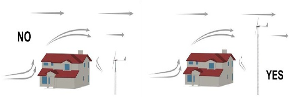
When the wind is eclipsed by the objects it finds in its way, it reduces its speed and results in turbulences. A wind mill installed on the wrong place will not perform as it would in a non- influenced place.
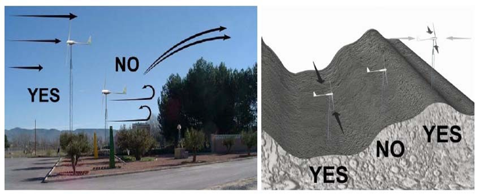
To maximize the performance of your wind turbine, it should be installed the farthest away possible from the obstacle and over a tower higher of this obstacle.
If the wind mill is going to be installed in a valley, it should be done on the top where it will catch the wind from any direction or on the bottom where the wind is canalized.
* All specifications are subjected to change without any notice
Warranty
Limited warranty
Your new USCET Wind Mill is guaranteed against any material defect. This warranty does not include other equipment or accessories that could be involved in the preparation of the wind mill. The warranty does not include defects or damages produced by an inadequate use or installation of the product.
Warranty Period
The warranty period for the USCET wind turbines and their components is 12 months from the date of original installation or 15 months from delivery date, whichever is earlier against faulty workmanship and defective materials.
Warranty – for Accessories
The warranty period for the USCET wind turbines accessories is 12 months from the date of original installation or 15 months from delivery date.
Warranty Conditions
Needs to be informed the installation date to USCET through mail / phone without fails.
The warranty includes replacement of defective pieces and job repair in our factory. The items to be repaired must be sent to our factory, the sender (or owner of the USCET defective Wind Mill) will be responsible for all mailing charges.
The warranty excludes damage ports (tower).
USCET reserves the right to change the pieces as we see fit.
Any wind mill excluded from the warranty conditions will be repaired and sent back. These repair costs will be charged/billed.
Model – 120 – Watts
|
Rated Power - Watts |
120 |
|
Rated Wind Velocity m/sec |
10.5 |
|
Cut in Wind Velocity m/sec |
2.5 |
|
Turbine Height m |
1 |
|
Turbine Width m |
0.4 |
|
Turbine Diameter m |
0.6 |
|
Turbine RPM |
250 |
|
Alternator |
Permanent Magnet |
|
Output Voltage DC |
24 or 48 |
Model – 1000 – Watts
|
Rated Power - Watts |
1000 |
|
Rated Wind Velocity m/sec |
10.5 |
|
Cut in Wind Velocity m/sec |
2.5 |
|
Turbine Height m |
2 |
|
Turbine Width m |
0.9 |
|
Turbine Diameter m |
1.3 |
|
Turbine RPM |
150 |
|
Alternator |
Permanent Magnet |
|
Output Voltage DC |
24 or 48 |